Voltage Divider Calculator | 2 & 3 Resistors, Current & Power Dissipation
A voltage divider, also known as a potential divider or voltage splitter, is a simple passive linear circuit that produces an output voltage () that is a fraction of its input voltage ().
The core of a voltage divider is the use of two or more resistors connected in series. As current flows through these resistors, a voltage drop occurs across each resistor based on its resistance value. The voltage is divided proportionally between the resistors.

Why Use a Voltage Divider?
- Voltage Reduction: The primary use is to reduce a higher voltage level to a lower one that’s suitable for a specific component or circuit. For example, you might need to drop a 9V battery supply down to 5V to power a microcontroller.
- Sensor Reading: Many sensors output a variable voltage. Voltage dividers allow you to bring that voltage within the readable range of an analog-to-digital converter (ADC).
- Signal Conditioning: They can be used to scale down analog signals for further processing.
- Bias Circuits: Used in transistor circuits to establish proper operating points.
Types of Voltage Dividers
1. 2-Resistor Voltage Divider
This is the simplest and most common configuration, using two resistors ( and ) connected in series to an input voltage.
Circuit Description:
Input voltage () is applied across both resistors. The output voltage () is measured across .
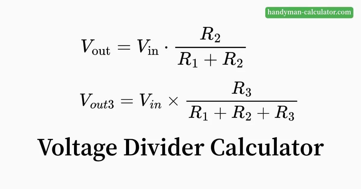
Formula: The output voltage is calculated as follows:
Where:
- =Output Voltage
- =Input Voltage
- =Resistance of the first resistor (connected to the input voltage)
- =Resistance of the second resistor (connected to ground)
Key Points
- Voltage Splitting: The resistors divide the input voltage proportionally to their resistance values.
- Resistor Selection: Adjusting and determines the output voltage.
- Power Dissipation: Ensure resistors can handle the power dissipation to avoid overheating.
Example 1: 2-Resistor Voltage Divider
Input voltage () = 12V, :
Output voltage () = 4V.
2. 3-Resistor Voltage Divider
A 3-resistor divider provides more flexibility and uses three resistors connected in series.
Circuit Description:
Input voltage () is applied across all three resistors (). The output voltage () can be measured across or between and .
Formulas:
Output voltage across :
Output voltage between and :
Example:
Input voltage () = 15V, :
Output voltage across = 7.5V.
How to Use Our Online Voltage Divider Calculator
- Choose Configuration: Select between a 2-resistor or 3-resistor voltage divider.
- Enter Input Voltage (): Input the source voltage value.
- Enter Resistor Values: Specify the resistance for each resistor (e.g., in ohms, kiloohms, or megaohms).
- Click Calculate: Instantly compute the output voltage () and the circuit current.
- View Results: See the calculated output voltage and circuit current clearly displayed.
Key Considerations When Designing Voltage Dividers
- Load Impedance: The connected circuit can affect the output voltage. A low load impedance may draw current and alter the expected behavior.
- Current and Power Dissipation: Account for current and heat dissipation in the resistors.
- Resistor Tolerance: Variations in resistor values (e.g., 1% or 5% tolerance) may slightly affect output voltage.
- Resistor Value Selection: Balance resistance to ensure neither too low nor too high current flow.
Applications of Voltage Divider Circuits
- Sensor Interfacing:
- Adjust sensor output levels to match the input range of microcontrollers or ADCs.
- Example: Interfacing a thermistor in temperature measurement systems.
- Reference Voltages:
- Generate a reference voltage for amplifiers or comparator circuits.
- Voltage Scaling:
- Reduce high voltages for safe measurement or operation with lower-voltage devices.
Voltage dividers are ideal for scaling sensor outputs. For long-distance sensor wiring, prevent power loss with our Voltage Drop Calculator.
FAQs
Can I use a voltage divider to power a device?
No, voltage dividers are not suitable for powering devices with significant current requirements. For such cases, use voltage regulators.
What is the ideal resistor value for a voltage divider?
The resistor values depend on your application: * Higher resistances minimize power loss but are more susceptible to noise. * Lower resistances provide better stability but increase power consumption.
Conclusion
Voltage dividers are essential building blocks in electronics. By understanding their principles and using our online calculator, you can design circuits to achieve desired voltage levels. Whether for sensor applications, voltage reduction, or signal conditioning, a good grasp of voltage dividers is invaluable. Experiment and keep designing!
Voltage Divider Calculator
Calculate voltage division across multiple resistors. Results include node voltages, current flow, and power dissipation.